External GPIO Pinmap — Rev 1.1
This page covers the external expansion header pinmap for the XM10 Rev 1.1 board. Eight digital I/O (DIO) pins and four dedicated analog input (ADC) pins are available by default. Any of the eight DIO pins can be dynamically switched to ADC mode at runtime, giving you up to 12 ADC channels total.
For the API (function calls) to use these pins, see External IO API. This page focuses on board pin layout.
Header Location
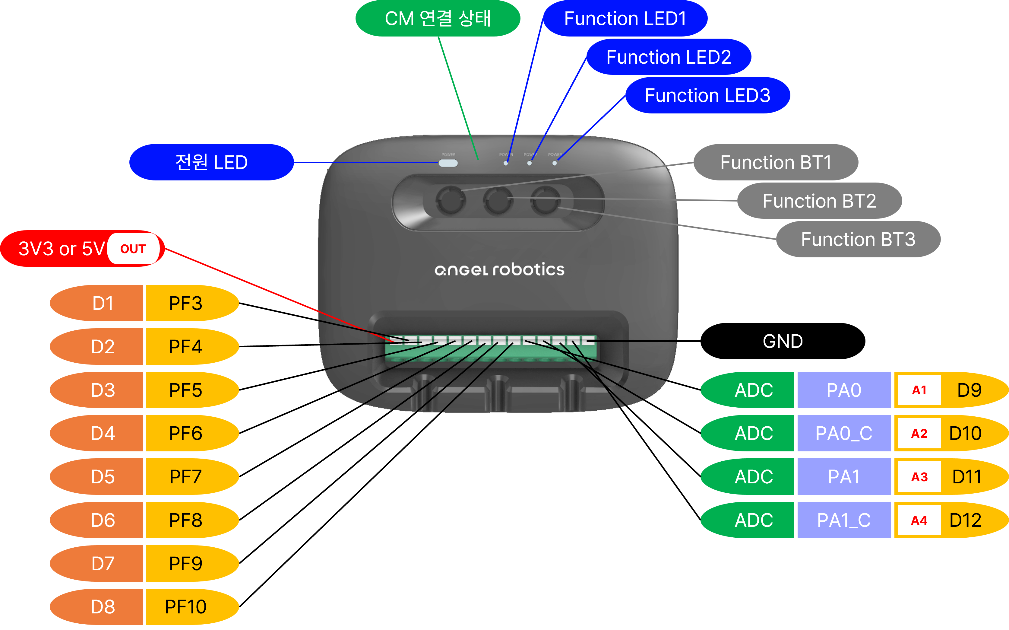
Use the photo above to locate the external GPIO header (DIO 8 + ADC 4) on the Rev 1.1 board and to identify which end is pin 1. Refer to the tables below for per-pin functions.
DIO 8 Pins
| API Name | PCB Label | Default Mode | Notes |
|---|---|---|---|
XM_EXT_DIO_1 |
EXT_GPIO_1 | Digital | Can be dynamically switched to ADC |
XM_EXT_DIO_2 |
EXT_GPIO_2 | Digital | Can be dynamically switched to ADC |
XM_EXT_DIO_3 |
EXT_GPIO_3 | Digital | Can be dynamically switched to ADC |
XM_EXT_DIO_4 |
EXT_GPIO_4 | Digital | Can be dynamically switched to ADC |
XM_EXT_DIO_5 |
EXT_GPIO_5 | Digital | Can be dynamically switched to ADC |
XM_EXT_DIO_6 |
EXT_GPIO_6 | Digital | Can be dynamically switched to ADC |
XM_EXT_DIO_7 |
EXT_GPIO_7 | Digital | Can be dynamically switched to ADC |
XM_EXT_DIO_8 |
EXT_GPIO_8 | Digital | Can be dynamically switched to ADC |
Electrical specifications:
- Input / Output: 3.3 V logic
- Internal pull-up / pull-down resistors: supported (select via XM_SetPinMode)
ADC 4 Pins (Fixed)
| API Name | PCB Label | Notes |
|---|---|---|
XM_EXT_ADC_1 |
EXT_ADC_1 | 12-bit native (ADC1), analog input only |
XM_EXT_ADC_2 |
EXT_ADC_2 | 16-bit native (ADC2), analog input only |
XM_EXT_ADC_3 |
EXT_ADC_3 | 12-bit native (ADC1), analog input only |
XM_EXT_ADC_4 |
EXT_ADC_4 | 16-bit native (ADC2), analog input only |
Electrical specifications:
- Input range: 0 – 3.3 V
- Resolution: XM_EXT_ADC_1/_3 = 12-bit native (ADC1), XM_EXT_ADC_2/_4 = 16-bit native (ADC2) — function output supports 8/10/12/16-bit selection
- Sampling rate: 10 kHz
DIO → ADC Dynamic Switch (8 Additional Channels)
Switching a DIO pin to ADC mode at runtime gives you up to 12 ADC channels. Call XM_SwitchDioToAdc(), then read with XM_AnalogRead(XM_DIO_TO_ADC_PIN(dio)).
| API After Switch | Original DIO |
|---|---|
XM_EXT_ADC_5 |
DIO 1 |
XM_EXT_ADC_6 |
DIO 2 |
XM_EXT_ADC_7 |
DIO 3 |
XM_EXT_ADC_8 |
DIO 4 |
XM_EXT_ADC_9 |
DIO 5 |
XM_EXT_ADC_10 |
DIO 6 |
XM_EXT_ADC_11 |
DIO 7 |
XM_EXT_ADC_12 |
DIO 8 |
Once switched, the pin stays in ADC mode until the board is reset — this is intentional safety behavior.
Notes on External IMU Usage
Activating an external IMU (e.g., XSENS MTi) via XM_AttachXsensMTi630() reassigns some pins to UART.
For activation details, see External IO API — External IMU Control
Common Issues
| Situation | Solution |
|---|---|
| ADC always reads 0 or 3.3 V only | Missing pull-down resistor or short circuit. Check the FSR voltage-divider circuit (FSR — DIO pin — 10 kΩ — GND) |
| Cannot switch back to DIO after switching | Reset the board or cycle power (intentional safety behavior) |
DigitalWrite has no effect |
The pin has been switched to ADC mode. ADC pins must be accessed through the ADC API only |
| High ADC noise | Use short jumper wires and a common GND; add an external RC filter if needed |
Related
- Overall hardware overview: hardware/README.md
- Rev 2.0 pinmap: external-gpio-rev2.0.md
- Function reference: External IO API
- Hands-on examples: Ex.04 – 05d Ext IO series